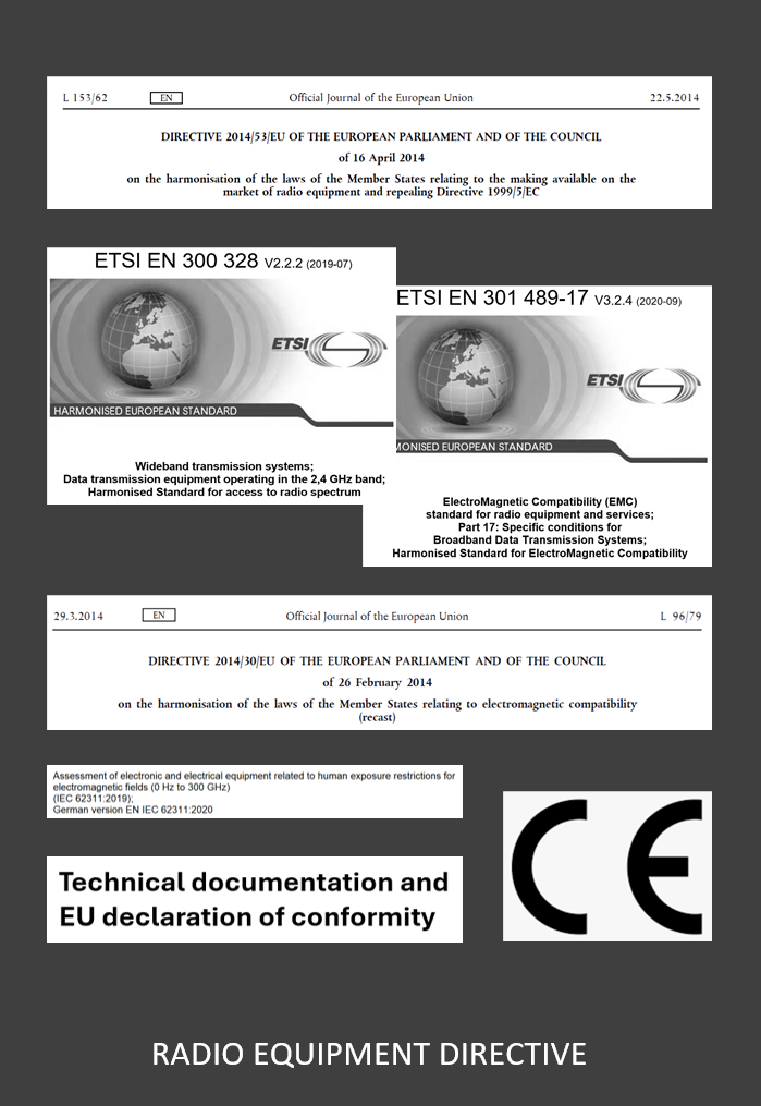
Before things get technical, here are the procedures that must be followed:
Companies must comply with the Radio Equipment Directive when selling their radio products on the European Market. This is illustrated on the left side.
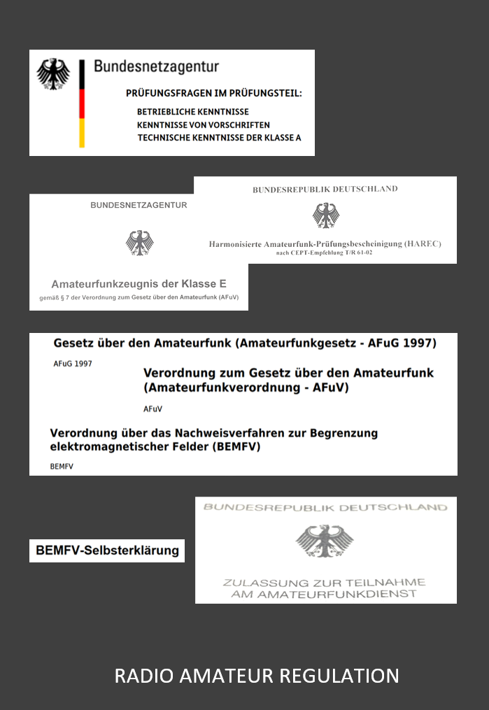
Anyone who wants to become a radio amateur must take exams at the BNetzA in Germany and must adhere to rules when setting up their station and
communicating. See the picture on the right.
The following applies to both: Everyone is fully responsible for their actions and must follow the rules. Otherwise radio communication would not
be possible!
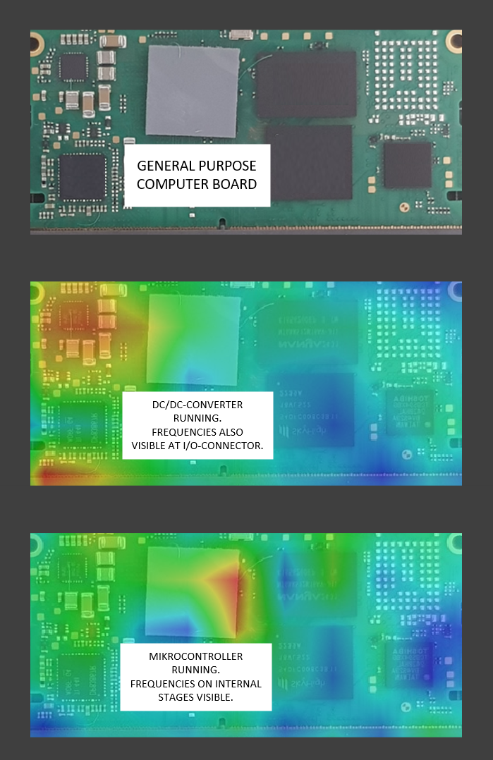
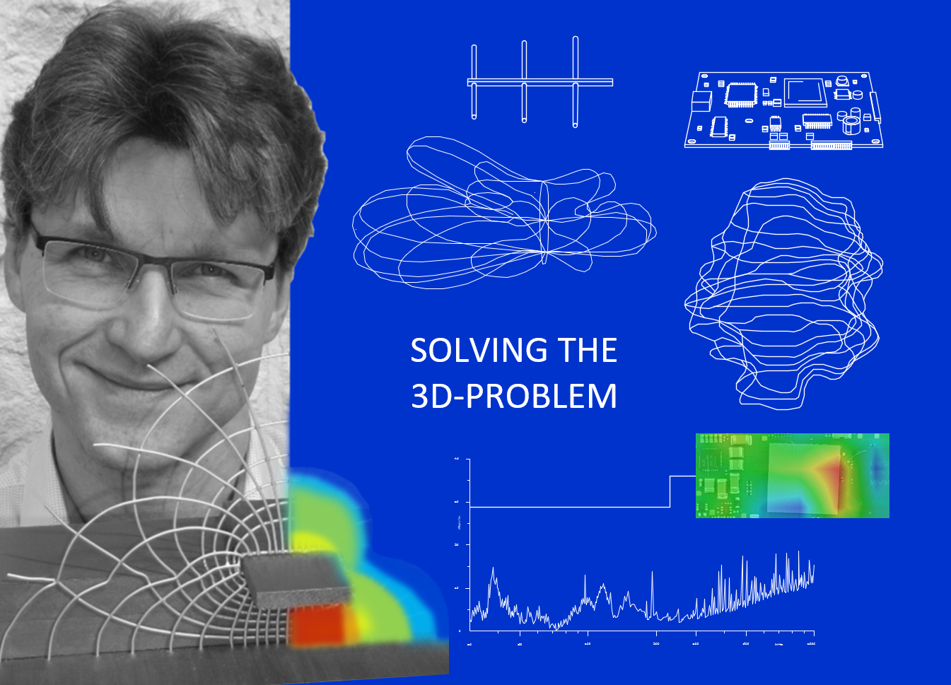
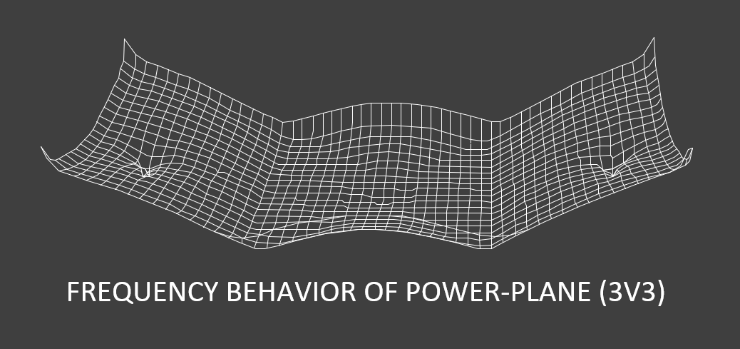
Let's take a look at the frequency behavior of a plug-in mikrocontroller board that is build into a software defined radio.
The questions would rise "How does it interact with the main PCB and which frequencies will be generated?"
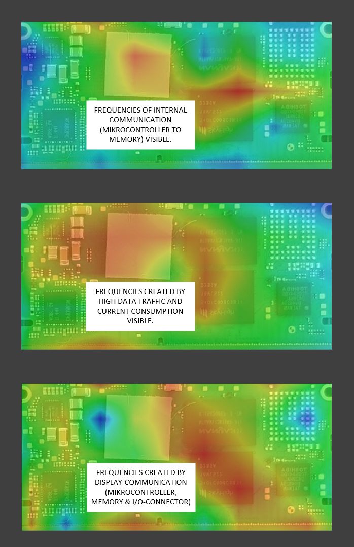
Each circuitry such as the DC/DC-converter, the internal activity of the microcontroller and the data flow between
the memory modules provides its frequency contribution.
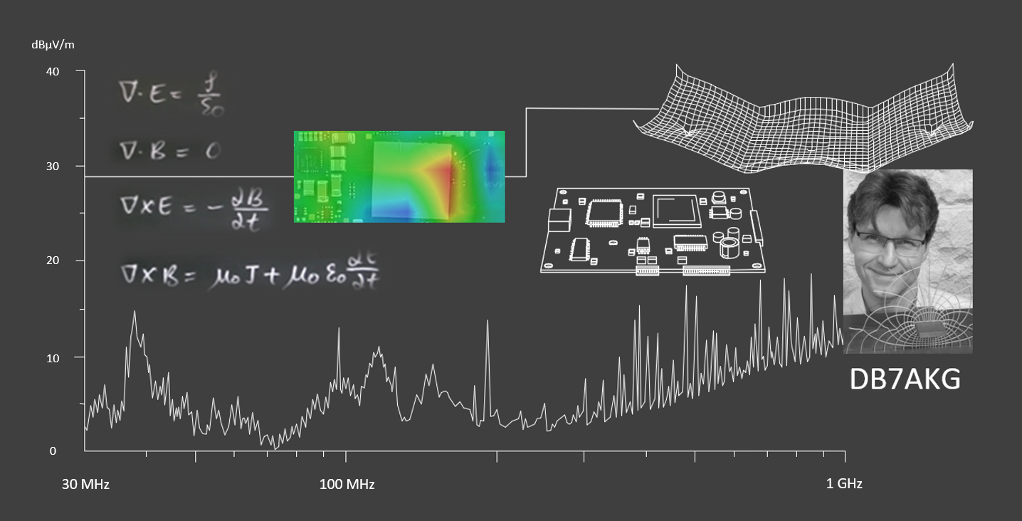
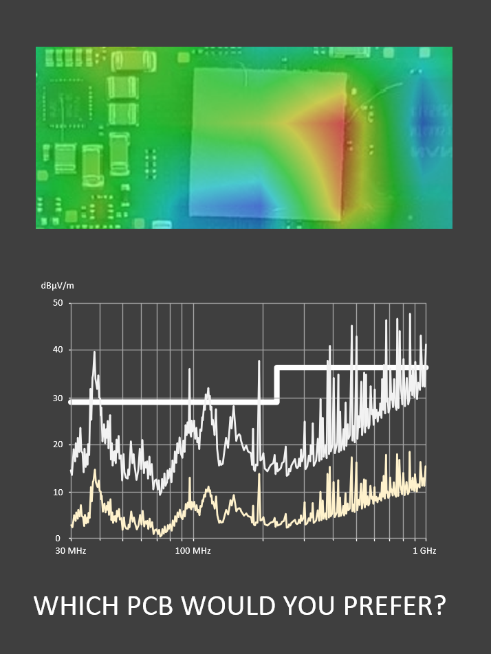
By measuring the electromagnetic fields and displaying them in colored areas, a well-founded statement about the EMC behavior can be made.
Here the concept of "MAKE EMC VISIBLE" becomes clear!
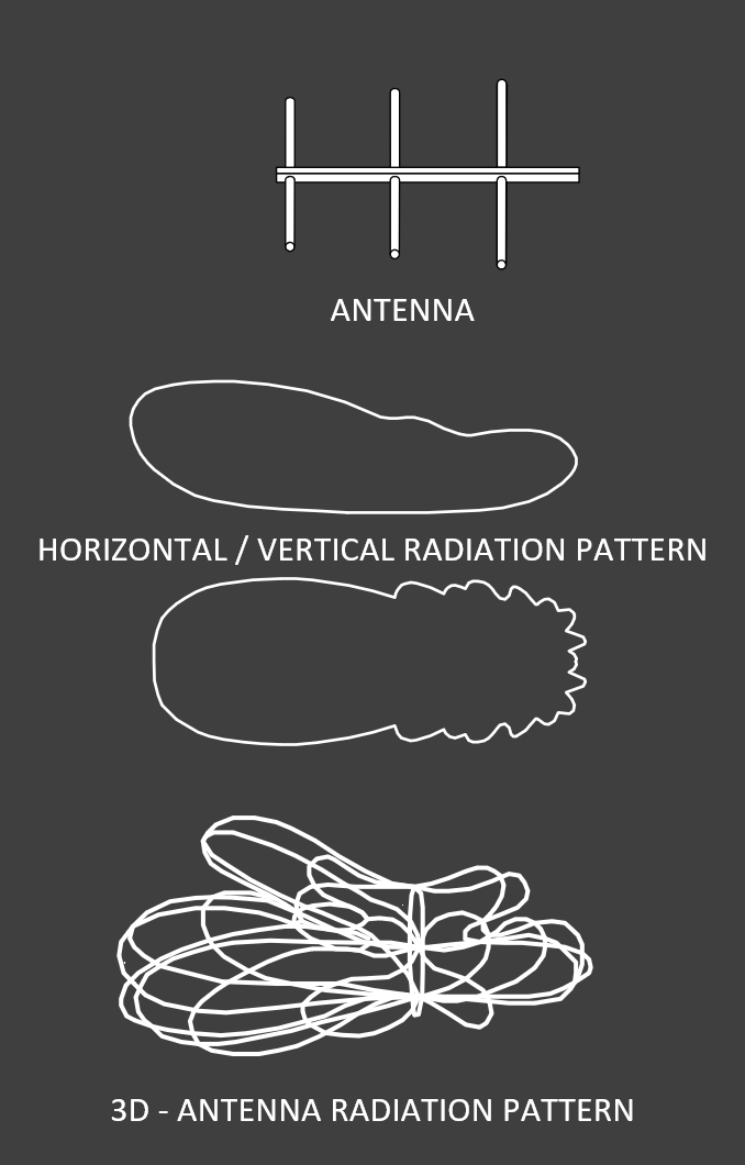
Radio amateurs are familar with antennas. Some even build some of them themselves. Horizontal and vertical antenna patterns are also nothing new for them.
But things get really interesting with 3D representations.
These have to be simulated or measured. See the picture on the left.
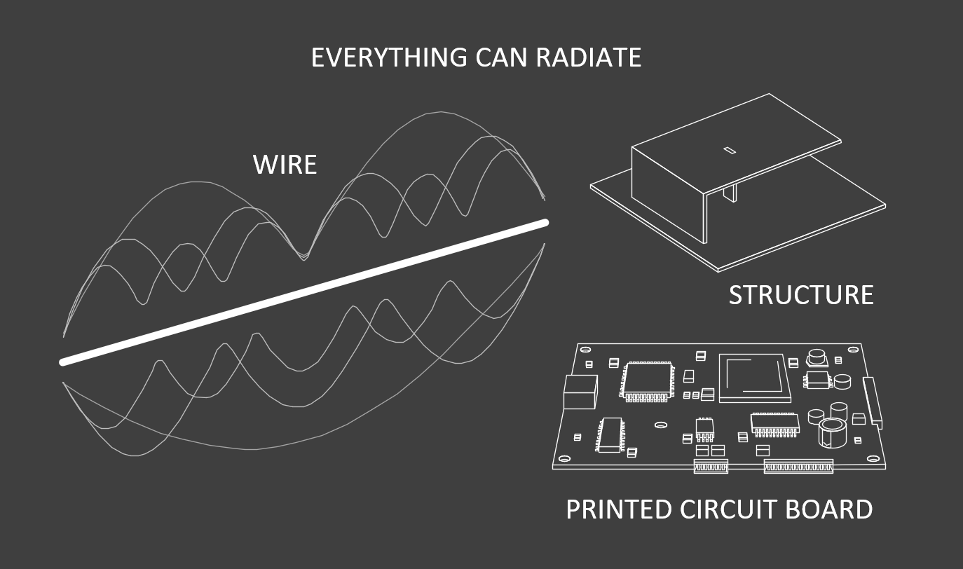
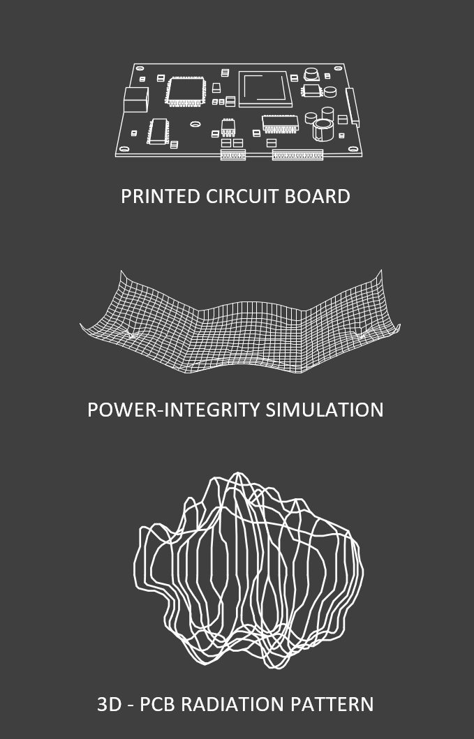
Printed circuit boards (PCBs) also represent antennas, even if the developers or project managers do not want to admit it!
A well-thought-out PCB design is characterized not only by the inclusion of Signal-Integrity, but also by focusing of the Power-Integrity.
The electromagnetic energy generated on the PCB must be guided clearly and unavoidable radiation must be minimized!
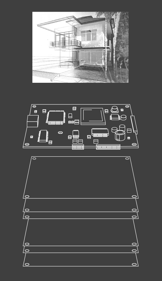
Anyone who has ever built a house knows what I am talking about. The same applies for PCBs! Like the floors of a house, the different layer must be
selected wisely.
The goal of an EMC-compliant PCB-design is "first time right". Impossible? Not if you have experience!
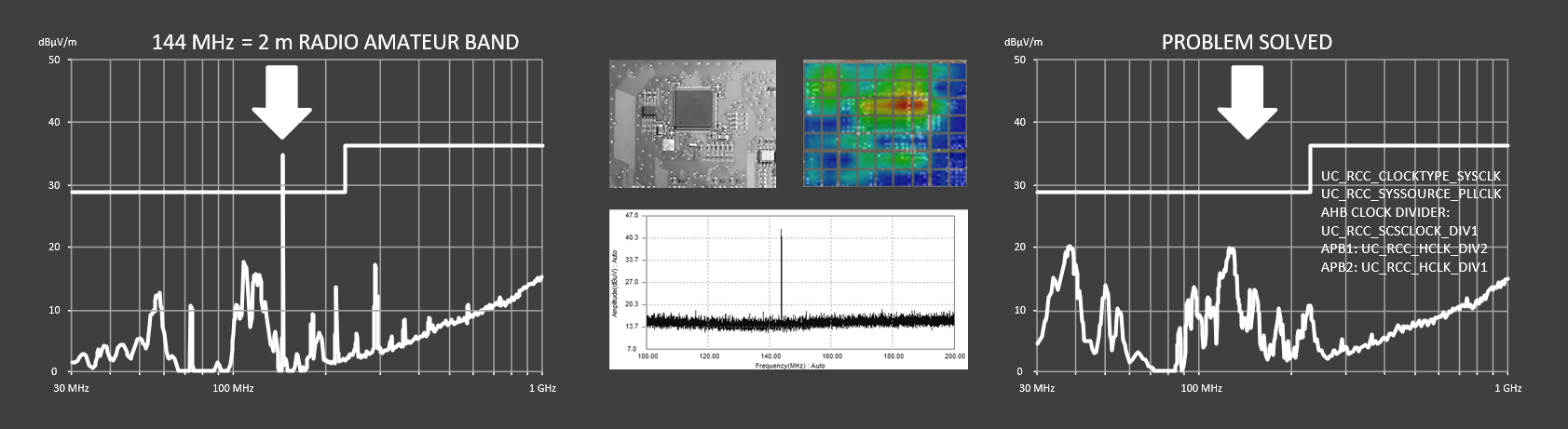
Measuring and visualizing electromagnetic fields is very helpful in this regard. Interfering frequencies can be detected and improvements can be made.
If you need further information how to "MAKE EMC VISIBLE", please contact me!
Simulations have become important in modern development. Radio amateurs can also benefit from this.
However, a simulation is only ever as good as its models. Experiences are just as important and indispensable!
Not every antenna is available as a model, and the environment as well as the frequency range to be used also play a decisive role. Naturally, every radio amateur wants to know the characteristics of their antenna given the chosen setup.
Here, too, it is important to adhere to the building regulations regarding the installation and to ensure safety.
Skilled craftmensship is also required. This pays off when the antenna can be installed exactly as planned. An example of the diverse requirements associated with amateur radio!
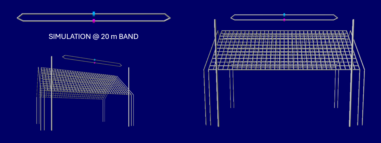
Shown below is a simulation of a T2FD antenna that I use personally and with which Japan and New Zealand can be reached, depending on radio conditions.
This antenna was developed by the US military. It is very broadband and features a terminating resistor.
Opinions on this antenna are divided. For me, it’s a good starting point for creating my own simulations.
Let us look at the antenna in the picture below, as well as its construction and its surrounding.
It is supported by two metal masts, which in turn are connected to the lightning protection system.
This marks the first point of interaction between the antenna and the metal masts that can influence the antenna pattern.
Furthermore, the question arises as to the extent to which other metallic structures (e.g. lightning protection,
accessible mounts, and the planned mounting for the Yagi antenna) might influence the antenna characteristics.
Also, a statement can be made if the roof were of metallic construction.
The picture below shows the simulation model, as well as the masts and the house with a metalic surface-finish.
The illustration shows excerpts from the simulation - in this case, using the 20-meter band.
Next, the antenna's free-space radiation pattern is shown - with the masts mount only - followed by the installation site,
including lightning protection and finally a full-surface metal roof finish.
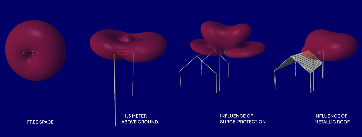
Most people won't realize just how drastically the antenna's radiation pattern changes! This applies to the radio amateur, but also to the "professional developer"!
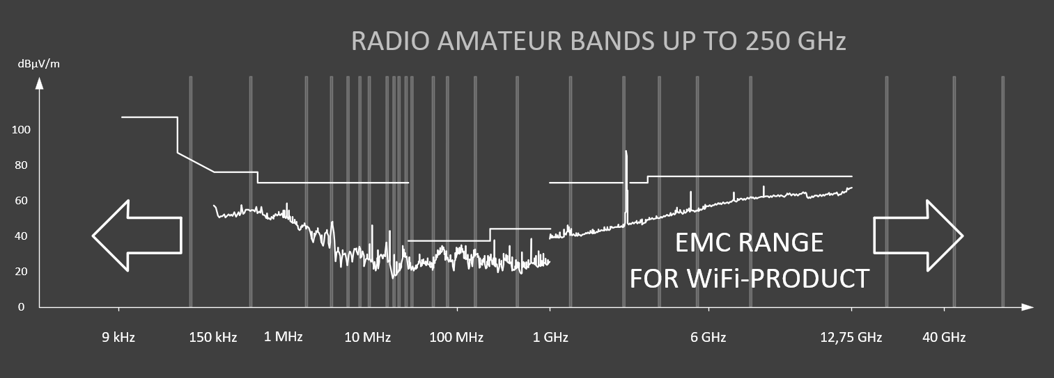
Whether at home or in the field of installation - and across a range of frequencies, from the 135 kHz to 250 GHz amateur radio spectrum as well as to the 2.4 GHz band used for industrial IoT devices (Wi-Fi, Bluetooth, ZigBee, Matter, etc.) – the radiation pattern to be achieved is a critical factor.
This determines not only success in DX contests involving worldwide radio contacts but is also essential for every radio product placed on the market!
The effort is worthwhile and forms the basis for the targeted development of your antenna or the „professional“ radio products.
I am happy when I pass on knowledge and the participants can put it into practice. I was able to implement this in many events, such as the EMC
trade fair in Stuttgart, workshops in STEM (MINT) topics like electronics and robotics at VDI Tecstatt, and lectures in the amateur radio sector.
Practical examples and demonstrators provide participants with understandable insights into the world of EMC-compliant electronic design.
Contact me, if you are interested in a workshop.
Important: The placement is carried out in accordance with the Code of Business Conduct (CoBC).

Thank you for taking the time to read my homepage. I would be happy if you have gained new insights and ideas!
I am glad to hear from you. Please use the contact template. If time permits, I will of course reply!
Vy 73, Andreas, DB7AKG